An XYZ linear slide is a three-axis linear motion system that provides controlled movement along the X, Y, and Z axes. It is commonly used to position tools, workpieces, sensors, grippers, or other equipment within a three-dimensional workspace.
Unlike a single-axis linear slide, an XYZ linear slide combines three linear motion axes into one coordinated system. This allows automated equipment to perform positioning and movement in multiple directions without requiring a conventional industrial robot.
For OEMs and automation system integrators, a custom XYZ linear slide can be configured according to the required stroke, payload, speed, accuracy, mounting method, and working envelope.
The basic advantage of an XYZ linear motion system is its ability to provide movement in three directions.
The three axes can operate independently or be coordinated to achieve the required motion path.
This makes XYZ linear slides suitable for applications requiring accurate positioning within a defined three-dimensional workspace.
An XYZ linear slide can be built by combining different linear motion components.
Depending on the application, the system may use:
The configuration can be selected based on the required speed, load, stroke, accuracy, acceleration, and duty cycle.
One of the most important benefits for OEM customers is the ability to customize the travel of each axis.
For example:
| Axis | Typical Requirement |
|---|---|
| X Axis | Long horizontal travel |
| Y Axis | Cross positioning |
| Z Axis | Vertical lifting or lowering |
The three strokes do not need to be identical.
A custom XYZ linear slide can therefore be designed around the actual working envelope of the machine instead of forcing the customer to adapt the equipment to a standard size.
Different applications require different payload capacities.
The required load should include not only the workpiece but also the equipment mounted on the moving axis.
This may include:
For a custom 3 axis linear stage, the Z-axis is particularly important because it must account for vertical load, acceleration, and the moment generated by the tooling.
An XYZ system can provide repeatable positioning at predefined coordinates.
This makes it useful for applications where a tool or workpiece needs to move between multiple points.
Depending on the mechanical configuration, control system, encoder and application requirements, different levels of positioning performance can be achieved.
For precision applications, the complete system should be evaluated rather than looking at the linear module alone.
An XYZ linear slide system can be integrated with a wide range of automation equipment, including:
This makes XYZ linear motion suitable for both standalone machines and larger automated production lines.
An XYZ linear system and an industrial robot are designed for different types of motion.
| Feature | XYZ Linear Slide | Industrial Robot |
|---|---|---|
| Motion | X/Y/Z linear | Multi-axis articulated |
| Working path | Structured Cartesian movement | Flexible spatial movement |
| Programming | Relatively straightforward | More complex |
| Payload customization | High | Depends on robot model |
| Workspace | Rectangular/Cuboid | Irregular robotic workspace |
| Integration | Easy for Cartesian applications | Suitable for complex motion |
| Best for | Pick/place, dispensing, inspection, handling | Welding, assembly, complex manipulation |
When the application mainly requires straight-line X/Y/Z movement, an XYZ linear slide can provide a simpler and more structured alternative to a six-axis robot.
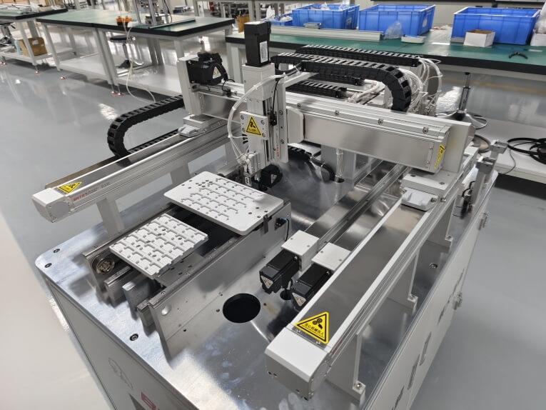
One of the most common applications is automated pick and place.
The XYZ system can move a gripper or vacuum tool to a specific X/Y position, move vertically along the Z-axis, pick up a product, and transfer it to another location.
Typical applications include:
An XYZ linear stage can move a dispensing nozzle along programmed paths.
Applications include:
The linear structure provides a controlled motion path that can be synchronized with dispensing equipment.
XYZ linear slides can position cameras or inspection sensors at different locations.
A customized system can move the inspection head along the X, Y, and Z axes to inspect multiple points on a product.
Applications include:
An XYZ linear slide can be used to load and unload parts from production equipment.
For example, the system can move a gripper:
Loading Position → Machine → Processing Area → Inspection → Unloading
This makes Cartesian linear motion suitable for CNC machine tending and other repetitive handling applications.
A 3 axis linear stage can position components during automated assembly.
Typical operations include:
For applications requiring rotational movement as well as linear movement, an additional rotary axis can be integrated.
XYZ motion systems can position laser heads relative to a workpiece.
Potential applications include:
The required accuracy, speed, rigidity, and environmental protection should be determined according to the laser process.
Standard XYZ systems may not meet the requirements of every automation project.
For OEM customers, the system can be customized around the actual machine design.
Possible options include:
The system can also be designed according to:
The Z-axis can be configured to support different tools, such as:
Before specifying a custom XYZ linear slide, OEM customers should provide several key parameters.
Define the required travel for each axis.
Calculate the complete moving mass, including tooling and workpiece.
Determine the required maximum speed and production cycle time.
High-cycle applications may require higher acceleration and greater structural rigidity.
Define whether the application requires standard positioning or precision positioning.
Consider:
The system may be integrated with:
For OEM equipment, the best linear motion solution is usually determined by the complete machine rather than by a single component.
A customized XYZ linear motion system can be optimized for the customer's:
Product + Process + Workspace + Cycle Time + Payload + Accuracy
This approach can help avoid unnecessary oversizing while ensuring that each axis has the required mechanical performance.
For example, a long X-axis may be combined with a shorter Y-axis and a compact Z-axis. The motor, guide, transmission, and structural design can then be selected according to the requirements of each axis.