Linear motion does not always have to follow a straight path. In many automated production systems, products, fixtures, or carriers need to move along a curved, circular, or customized trajectory.
A Curved Linear Guide provides a guided motion solution for applications where conventional straight linear guides cannot meet the required movement path.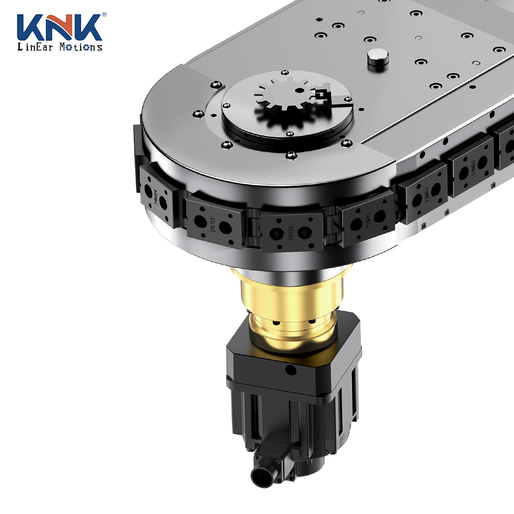
For OEM machine builders and automation integrators, a custom curved linear guide system can be designed according to the required radius, track length, load, carrier dimensions, speed, installation space, and production process.
Curved guide systems can be used in circular conveyors, elliptical conveyors, inspection equipment, assembly machines, automated handling systems, and specialized motion mechanisms.
A Curved Linear Guide is a guiding mechanism designed to support and control movement along a curved path rather than a conventional straight axis.
Depending on the application, the guide can follow:
A typical system may consist of:
The guide rail determines the movement path while the carriage or carrier follows the predefined curve.
Standard linear guides are designed for straight-line motion. They are highly effective when the application requires movement along a single axis.
However, some automation systems require products to change direction continuously.
For example:
Straight → Curve → Straight → Curve
In this situation, a curved guide system can provide a more integrated solution.
Potential advantages include:
OEM customers often have machine layouts that cannot be accommodated by standard guide rail dimensions.
A custom curved linear guide can be designed around the customer's application.
Customization may include:
The guide can be designed according to the required curve radius.
The total guide length can be matched to the machine layout.
Depending on the application, the guide may form:
The carrier can be customized for the product or fixture.
The guide system can be selected according to the total moving load.
The main difference is the movement path.
| Feature | Curved Linear Guide | Straight Linear Guide |
|---|---|---|
| Motion Path | Curved | Straight |
| Radius | Customizable | Not applicable |
| Circular Motion | Suitable | Not suitable |
| Closed-Loop Systems | Suitable | Usually requires multiple axes |
| Machine Layout | Flexible | Simple |
| Conveyor Integration | Excellent | Good |
| Customization | High | High |
| Typical Application | Curved motion, circular systems | Linear motion |
The choice depends primarily on the required motion trajectory.
One of the most common applications for curved guide systems is the circular conveyor.
A circular conveyor uses a guided track to move carriers around a closed-loop path.
A typical production process may be:
Loading → Assembly → Inspection → Testing → Unloading → Return
The curved guide sections control the carrier movement around the corners or circular portions of the conveyor.
For larger automation systems, curved guide sections can be combined with straight sections to create an oval or elliptical conveyor.
An elliptical conveyor typically consists of:
The guide system must allow carriers to transition smoothly between these sections.
A customized curved linear guide can be designed according to:
This makes it possible to build a continuous loop while maintaining controlled carrier movement.
A curved guide system can be integrated into automated assembly equipment.
For example, products can travel through several stations:
Product loading
Component placement
Fastening or dispensing
Vision inspection
Functional testing
Product unloading
The curved track allows the production line to use a continuous motion path while keeping the stations organized around the available machine space.
Inspection equipment often requires products to reach repeatable positions.
A curved guide system can transport carriers through multiple inspection stations.
Potential applications include:
When precise inspection positioning is required, the guide rail should be combined with an appropriate carrier and positioning mechanism.
Curved guide systems can also work with robotic pick-and-place equipment.
A robot can be installed beside the guide track to:
The guide system controls the product trajectory while the robot performs operations at predefined locations.
This approach can be useful when multiple robotic stations need to work around a continuous production loop.
For industrial automation, guide rail precision should be considered together with the complete system.
Important factors include:
If the guide is used for automated assembly or inspection, additional positioning mechanisms may be required.
The guide rail provides the motion path, while dedicated positioning components can provide more controlled station positioning.
The total load should be calculated before selecting the guide system.
The moving load may include:
Load distribution can also affect guide performance.
For example, a carrier with an off-center load may place additional forces on the guide system.
Therefore, OEM customers should provide both total payload and load distribution when requesting a customized design.
Operating speed is another important design parameter.
A curved track may create different mechanical requirements compared with a straight guide.
At higher speeds, engineers may need to consider:
The appropriate speed should therefore be determined according to the carrier design, radius, payload, and complete machine cycle.
A curved guide system often requires a dedicated carrier or carriage.
The carrier can be customized according to:
For production lines using multiple workstations, carrier design is especially important because the same carrier may interact with different automated tools.
OEM machine builders may need a guide system that fits directly into an existing machine structure.
A custom solution can be designed around:
This application-based approach is generally more effective than choosing a guide rail based only on standard dimensions.
When selecting a curved linear guide manufacturer, OEM customers should evaluate several capabilities.
The supplier should be able to evaluate:
The manufacturer should be able to customize:
For integrated applications, it is useful if the supplier understands:
A supplier with broader motion-control experience can better understand how the curved guide interacts with the rest of the machine.
For an accurate design and quotation, OEM customers should provide:
A simple CAD drawing or layout sketch can also help the manufacturer understand the application.
Custom curved guide systems can be used in:
A curved linear guide does not have to operate as an independent component.
It can become part of a complete automated motion system:
Curved Guide + Carrier + Drive System + Positioning + Robot + Production Station
For example, a customized elliptical conveyor may combine curved guide sections with straight guide sections and a chain or belt drive.
This creates a continuous motion platform for automated manufacturing.
A Curved Linear Guide provides a flexible solution for automation applications where movement cannot be limited to a straight path.
By customizing the radius, track geometry, length, carrier, payload, speed, mounting structure, and positioning system, the guide can be adapted to circular, oval, elliptical, and other specialized motion applications.
For OEM machine builders, curved guide systems can support circular conveyors, elliptical conveyors, automated assembly, inspection, testing, pick and place, and material handling.
The correct guide should be selected according to the complete application rather than one parameter alone. Payload, radius, speed, carrier design, positioning requirements, cycle time, and installation conditions should all be considered during the design process.
For customized industrial automation projects, working with an experienced Curved Linear Guide manufacturer can help OEM customers develop a guide system that integrates effectively with the complete machine.